
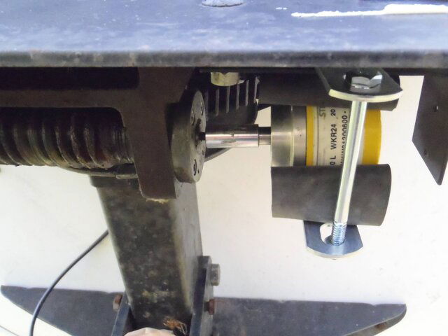
I came up with a simple circuit for running a rotary encoder for higher resolution. I went with a Motorola 8103 Isocoupler because I had several that came out of old IBM Servers. I used 4 1N4001's to make a bridge and a 5 volt regulator so I could tap into any power I found onboard. The large cap is for DC smoothing. The red LED is power, the yellow LED is the pulse. The circuit can handle 1000 pulses per rotation easy, but 48 is working great.
The install: This particular install is in a VBox-X (It also worked in a VBox VII) Inside the VBox-X I found a nice 11V AC right of the transformer. I soldered here for power. The other connections were even easier. I unsoldered the two black signal leads to attach to my board then ran my converted isocoupler output to other circuit board. I ran the 5 volts for the isocoupler to the outside connecions that were no longer needed. This left only one more connection. The pulse signal coming back from the encoder. I ran a 20 AWG stranded from my board right out the opening for the existing signal connection. No new holes in the box, and everything could be put back to perfect original if needed.
One bonus with the VBox-X that the VBox-VII lacked, was the nice tinted display cover. This allows the power and Pulse LED's on the board to show VERY NICELY! Sorry, the camera screwed up that pic. But if you have ever seen the VBox-X, you know exactly what I mean. Below are a picture of the board by itself, and installed in the VBox-X.
I need to thank Satelliteguys.us user "Radio" for trusting me to tinker on the brand new box, for giving my space to tinker, and for buying the parts I needed. Also, a special thanks to users "nicknjen". Nick for the Rotary Encoder idea and for beta testing the circuit all last month, and Jen for patiently allowing the beta test.
If I failed to give enough info on how to do this yourself, I appologize. I will be glad to help with any questions. My friends have been hounding me to write up my projects for years. This is the first one I bothered to write up. Thanks to satelliteguys.us for a place to write it.
") Nick was really the one who started me on it. He knew the rotary encoder was the way to go, he was just not sure how to do a solid state circuit to tie it all togeather. I had a lot of fun on the project. I built a third one for another friend of a friend. He should have his birdview up and running it some time this week. I really love combining old with new. Keeping something out of a landfill, and now running better than it was ever designed to run. No relays, no mechanical switches... They should run for a VERY long time.
Nick was really the one who started me on it. He knew the rotary encoder was the way to go, he was just not sure how to do a solid state circuit to tie it all togeather. I had a lot of fun on the project. I built a third one for another friend of a friend. He should have his birdview up and running it some time this week. I really love combining old with new. Keeping something out of a landfill, and now running better than it was ever designed to run. No relays, no mechanical switches... They should run for a VERY long time. ")