Get the Best IPTV Service
OTHER - Old actuators and positioners | SatelliteGuys.US

OTHER Old actuators and positioners

armadillo_115

SatelliteGuys Pro
Original poster
Jun 10, 2015
1,342
1,063
Virginia
I did some trading. More details below. Actuators are a mixture of sensor types. Some are 5 wire controlled. Some are supposedly optical type. All stored inside for years in varying condition. Some may be good as-is, some needing repair. (Or just plain junk) Not sure when I'll get around to testing them.

Since I have never owned anything except for the reed type:
1) As I understand it, an unmodified VBox positioner will not work with optical or pot type actuator?

2) Regardless of sensor type, all can be tested only hooked to a car battery,correct? (Only the 2 power wires)

3) Paired with the correct type of stand-alone positioner, do optical and pot actuators function well enough to use without converting to a reed switch?

That's enough info to get me started with the testing phase I believe. I'll probably have lots more questions later. :coco

Ok, here's what info I saw with just a brief exterior look.

8 complete actuators, 1 motor. (2 look like 18", 6 are 24") (No broom handle arms in this bunch) :
2 Uniden UST-705
2 JGS Unknown model
Channel Master 6733 (Tagged as 'Only goes up'. So definitely has a defect)
SuperJack XL
SuperJack XL HQ
Channel Master Sat Systems (No other markings found yet)
* ProSat 118RX (This is motor unit only, no arm)


4 Positioner Boxes:
2 Channel Master Sat Scan 6250
Channel Master Sat Scan 6253
Arc Finder 15842 (?)

Thanks for any info/help!
 
  • Like
Reactions: FTA4PA and Brct203
The pot type (potentiometer) sensor must be used with that kind of controller. The Hall effect and optical (three wire) sensors can be adapted using a 5 volt reed relay to work in place of a reed switch. The Titanium ASC1 has an optional adapter for that purpose.
 
  • Like
Reactions: armadillo_115
congratulations on getting all those! Even if some work and some don't, sorting through that stuff and figuring it out is a fun project.

I too was given a bunch of old actuators. Some had spent years piled up under a deck, so had suffered from water damage.

later I got 2 others , which were VonWeise 24" in like-new condition, but with optical sensors. Another one which I got a few months later was a 24" VonWeise of the same type, with Reed sensor and a seized tube.

I first repaired what I could and was able to assemble a JGS 24" out of the pile of muddy and rusty actuators. It worked fine for a while and then started making a screeching sound, so I stopped using it but am keeping it as a spare.

Then I used the 2 optical VonWeise. One connected to my Drake analog receiver which I used as a positioner. No additional circuitry, I just used the +5V from the servo connection to power the optical sensor. It worked fine and was using that until last week. Now I just received one of the last ASC-1, and didn't want to buy the adapter, so i converted the sensor to reed. However, the other actuator which had the optical sensor gave me a bit of mysterious trouble. I was using it with an old MTI-2800 positioner. Very basic box with E and W buttons and a pulse counter. And while it seemed to work fine, I would notice a few hours later that it would have moved the dish by a few clicks. Not just false pulses which could be caused by static noise, but it actually moved the dish> I don't understand how that happened, but one day I took the magnet wheel and sensor from the seized VonWeise and used them in replacement of the optical stuff and that resolved the problem. It has worked reliably since then.

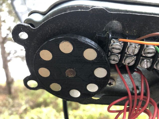
If you have access to a 3-D printer, it's reasonably easy to make a magnet wheel. You can either salvage old magnets from broken actuators, or in my case I used the small "rare-earth" magnets they sell at Harbor-Freight. The sensor is from an old JGS, but I think any Reed sensor would work if positioned properly. That last part was probably the trickiest part. Anyway it seems to work properly
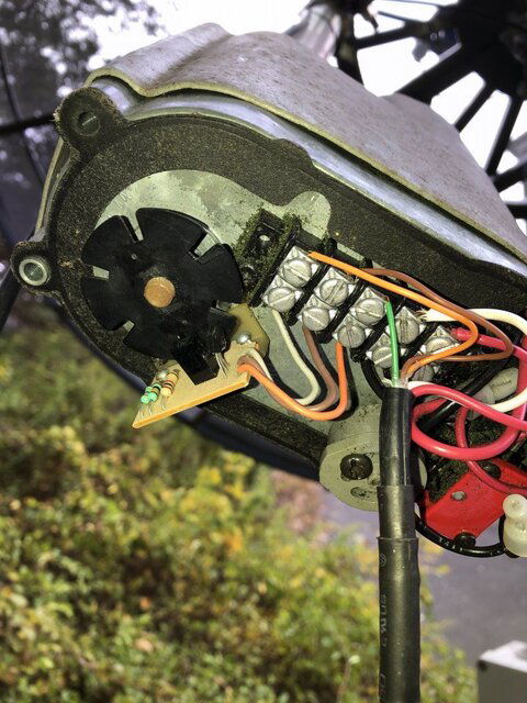
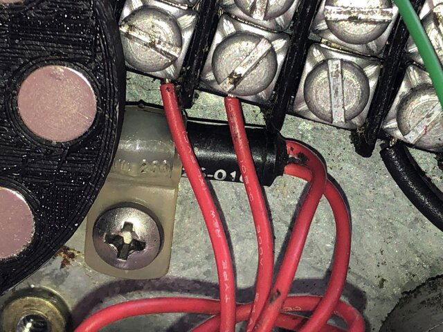
IMG_3794.JPG IMG_3796.JPG IMG_3797.JPG

Btw, one of the VonWeise weather cover that covers the motor assemble has "Uniden" written on it, so looks like Uniden was selling re-branded VonWeise
 
My goal.... other than to have spares.... is to get mamma's dish moving.

55W and 58W on HER stationary dish was 'all' she needed in the beginning. I now refer to that phase as the "FTA Honeymoon'. Life was goooood! Then she discovered channels she likes on other sats. Now she hogs MY dish and I never get the remote unless something needs fixing. :wtf:facepalm lol
 
Update:
Well, Mamma doesn't want the extra Sats when she can just watch on mine. :facepalm

So I'll leave it stationary for now.

I may switch to a C2-PLL dual output on my dish. That way she'll gain access to other sats thru my dish.

I still want one of these old actuators on her dish. (if any are good) That way I can adjust it at the dish using the car battery if needed.

I still need to re-route the cables so I can mow the yard easier, as discussed here:
Multiple cables and pipe in the same trench

Hey.... I'm only running behind 3 years on the trenching job. lmao

Btw: I was invited to join Procrastinators of America... But I was late returning my application.
 
Mamma may graduate to a motorized dish whether she wants it or not. :popcorn

QUESTION:
For the actuator motor wires.... would 16/2 lamp cord doubled be usable for the power cables? 230 feet run, pushing a 10 ft mesh. (Not a heavy 'glass dish) Got a good deal on 500 ft. It will be in pipe so I'm not worried about it being indoor wire.

Still looking for a bargain on shielded cable for the sensor wires.
 
I wouldn't do it at that length, even doubled up, AND especially if it's indoor wire. The reason(s) being two: 16 gauge @ 24 volts DC / 4amps and 230ft = 32% (almost 8 volts) DROP. So, that puts you at 16 volts. Not horrible IF it's a 24 volt actuator, but bad with an older 36 volt one, and likely means the wire will heat up.

Second reason is, that underground pipe will likely condensate water in it and fill up. Now you've got indoor wiring carrying electric current. IF there's even the slightest nick in the insulation, or it cracks after warming/cooling in weather, it'll could short out, possibly frying your positioner device. That's why we use sprinkler wire, or wire made for underground service, piped or not.

Even if it doesn't go to the point of frying things, why not use the proper wire to start with, so you don't have to do it over in a few years? IMO, saving a few dollars isn't worth that hassle, and also likely getting your wife pissed off when it fails.
 
FIRST... I'm not arguing. Second... I'm on a limited budget. :(

The figure I get with an on-line calculator is:
16g, 2 conductors in parallel.
24 Volt DC
230 ft
4.0 amps
---------------------------------
Voltage drop: 3.69
Voltage drop percentage: 15.39%
Voltage at the end: 20.31

* I've been running 170ft of ribbon cable that uses 16 gauge for the power cables w/o issue. I was figuring that combining 2 16's should go another 50 ft.
The top of the 'conduit' pipe will be flush with the ground, not buried. On a steep hill with lower end open. Any condensation will drain out.

I darn sure don't want to burn up a positioner though!

I appreciate any and all assistance!
 
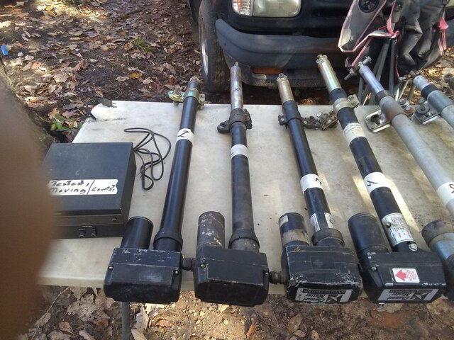
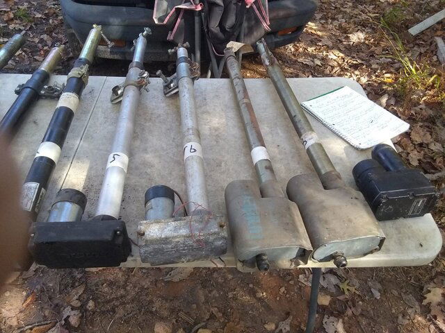
Here's the actuators. Numbered from left to right. Different order than in original post. 1st positioner box I picked up worked - Never tried other positioner boxes.(Not in photos)

Only tested for movement (briefly) using power wires. Sensors not tested. Approx measurements are for the main tube only. Below are preliminary test:

Actuators_1.jpg Actuators_2.jpg

Far left is the Channel Master Sat Scan 36 volt Positioner.
1) SuperJack XL HQ - 28" - 4 wire, Reed?. Motor runs but arm doesn't move. Can turn by hand but arm still doesn't move. Stripped out?
2) SuperJack XL - 22" - 4 wire, Reed? - Runs both direction.Lots of loose rust where motor couples to arm.... acme screw may be badly rusted.
3) Channel Master (looks like another SuperJack) - 25" - 5 wire, POT. -Runs both ways.
4) Channel Master (looks like another SuperJack) - 25" - 5 wire POT - Runs both ways. Tagged as "No count, only goes up" maybe POT is bad, IDK
5) JGS - 27" - 4 wire, Reed? - Motor runs both ways, but arm stripped out. - Don't see a limit switch. Low weight... prev owner said it is titanium. Maybe some salvage value if unfixable.
6) Identical model/condition to # 5 except motor makes more noise.
7)Uniden UST - 25" - 5 wire OPTICAL - Tagged as 'good' - Presumed Von Weiss motor like #8.Didn't pull down boot to check - Runs like a Cadillac. Super quiet and smooth.
8) Uniden, appears to be identical to #7 but markings unreadable - Von Weiss motor does NOT run - Optical sensor reading part is missing, wheel still there - Probably kept for spare parts - Arm moves freely when turned by hand.
9) ProSat 118 RX - Motor ONLY - Runs without an arm attached.

I figure 1, 5, 6, and 8 are low priority at this time due to condition. Will further test 2, 3, 4 and especially 7 when I get a 'round tu-it'. :rolleyes:
 
I installed the better Uniden UST actuator today with only power cables running to the Sat Scan positioner. Was too dark to do any more outside. It's so much quieter than my SuperJack....couldn't hear it running from the house and thought it wasn't working.lol.

I haven't greased it up or anything so I don't want to be motoring around much. I'll have to add sensor wires and decide on what positioner/sensor setup to use later.

Raining and spitting snow now. Temps gonna plummet after noon time. Brrrrrr!
 
Not to hijack this. Just completed my Superjack/ASC-1 mod last night and it's performing like a peach.
Superjack: Made my own magnetic encoder wheel from an old thin VCR gear and 3mm Amazon neodymium disc magnets. Used a printed and scaled 10 point star temp. glued to the gear to position the N pole side of the magnets around the perimeter. Then super glued 10 more S pole up. Buried the magnets in epoxy. Then drilled the center for the screw and swapped out the magnet.
Went through and lubed the motor. Used some nylon shim washers to take out the main gear slop where the encoder magnet is mounted.
Dremeled down an old Saginaw Hall sensor pc board to fit inside and yanked the reed switch. Used 6-32 machine screws for standoffs and drilled the gear cover to position the hall sensor over the encoder wheel. About 2-3mm spacing.
Crap. Hall sensor was toast. Living in the sticks has its disadvantages. Gutted a few old pc fans to find a hall sensor. Pulled up a few datasheets. The 4 pin ones work just fine.
One sensor pin is collector sink on N pole, the other is sink on S pole. Cool! Good for 35ma @ 12vdc. Swapped out the Saginaw sensor, tested. Bingo.
Scoped the pulse train while the motor was running. Nothing like Hall Effect Switches!
Drilled the bottom of the actuator housing and slapped in a zerk (about in the middle of the housing) and pumped in some -40F moly grease. Ran it in and out a few times. Very slick now.

ASC-1: I like Magic Statics Hall gizmo. I think I went one better. Crydom solid state relay. Fashioned one up. Input draws around 18-20ma @ 5vdc. It's just lighting up an led inside for a trigger. That's my Hall input from the motor. Output leads go to sensor terminals.
No worries, nice and neat. Got it all running last night with the snow flying late.
I don't know how many pulses per inch of travel but getting 10ppr on the encoder wheel. If I used the N pole output on the hall sensor also I could grab 20ppr. Don't think it's needed.
Worked out to 34 pulses per 2 degrees arc. So finding sats and storing positions was a breeze. The upper arc dropped a few pulses per 2 degrees.
It keeps counts perfect. That reed switch and main gear slop was driving me knutz. Haven't gotten that Von Weiss yet (not even sure if they have a 36" unit).

Photos if you want them. Will need to yank the motor cover though. The ASC-1 is pretty easy to get to.
 
I have a few more questions for you guys that are familiar with the older positioners. Not finding much info on-line:

Is there a way to determine if an old positioner box is pot type instead of optical type? I believe the Sat Scan 6250 and 6253 are for pots, but not positive. ( 5 cable hookups on back)

The Arc Finder positioner only has 4 cable hookups. Does that mean it is definitely for a reed switch type actuator? (IIRC, it is dated 1990 )

The Arc Finder and one of the Sat Scans only move in one direction. If I switch the motor wires, they only move in the opposite direction. Any ideas on the cause? (Testing done without sensor wires connected)

Thanks for any help!

I played a bit with the better Sat Scan today. Scanned in 40W - 58W. Moves well, need to get some sensor count working.
I'm impressed with that one Uniden UST (Von Weiss) actuator so far. :clapping
 
I have a few more questions for you guys that are familiar with the older positioners. Not finding much info on-line:

Is there a way to determine if an old positioner box is pot type instead of optical type? I believe the Sat Scan 6250 and 6253 are for pots, but not positive. ( 5 cable hookups on back)

Look in the above photos from Brct203. The one with metallic discs on the trigger wheel is a reed switch sensor. There are only 2 wires coming from the sensor to terminal strip.
If it were a hall effect type, the sensor (black cylinder next to the terminal strip and under the magnet disc) would have 3 wires coming from it.
The photo with the slotted wheel is an optical sensor of the thru beam type. One side of the sensor has an led that shines on the receiver on the other side of the U shaped module.
Pulses are generated when the slotted wheel blocks the sensor from 'seeing' the led. Pulses could be generated when light hits the receiver depending on design.
A pot style position sensor would have 3 wires and would be directly contacting a moving part of the actuator. Mechanical movement of the actuator changes resistance of the pot.
A multimeter would be used to check the condition of those. Analog (needle) meters show dead spots in the pot (wiper sweep) much easier than a digital meter. A spritz of Deoxit in the pot and working the wiper back and forth could rejuvenate a noisy or pot with dead spots.


The Arc Finder positioner only has 4 cable hookups. Does that mean it is definitely for a reed switch type actuator? (IIRC, it is dated 1990 )

I would think 2 wires from the sensor again would be a reed switch. Optical/Hall sensors require +vdc, common ground, and have a sensor output lead. Reeds just make/break contact.

The Arc Finder and one of the Sat Scans only move in one direction. If I switch the motor wires, they only move in the opposite direction. Any ideas on the cause? (Testing done without sensor wires connected)

Foggy on this one. You say that you hook up juice to the motor input and the motor goes one way. Hook up the wires in reverse and the motor goes the other way? That is correct then.
If it only goes one way but swapping wires wont make it reverse then it would be a bad or mis-adjusted limit switch or defective diode(s).
You could bypass the limit switch where the wires go directly to the motor and get it to go either way. Just be careful to not extend/retract too far or stall the motor.

I'm not specifically a pro with satellite actuators but do have a lot of industrial motion/feedback experience. If you don't have at lease a decent multimeter, the electrical diagnosis and repair will be a guessing game.


Thanks for any help!

I played a bit with the better Sat Scan today. Scanned in 40W - 58W. Moves well, need to get some sensor count working.
I'm impressed with that one Uniden UST (Von Weiss) actuator so far. :clapping
 
  • Like
Reactions: armadillo_115
Thanks for the info, Arlo. Sorry if I didn't explain it well enough.Let me try to clarify my questions better.

On the first question: I'm trying to determine what type positioner box I have. (I think I understand the visual difference between a pot, optical wheel, or reed switch on the actuator arm itself.)
For instance when looking inside a positioner box with 5 wire hookup: How can I determine whether it is compatible with a pot type.... or optical type actuator? I'm assuming they are not interchangeable. IDK? I'd rather not ruin an actuator or positioner. :coco

On the question about positioner boxes only moving one direction: It's like 1 relay is bad. Or maybe some other problem is causing ONE side of the positioner not to function? The 'good' box moves the dish in both directions, no problem.

It will be great if the ARC Scan Box is a reed switch type!
 
Hope somebody will chime in. I find no info on an ARC Scan at all. Not even a photo. Perhaps you could slap up a clear photo of the terminals on it for motor connection.
How about in the menu? Any selections for sensor type? Just 4 hookups to me would mean definitely a reed switch. 2 for motor, 2 for contacts. As far as one way direction only. Do you hear a relay click when you change directions? Perhaps 2 distinct clicks. Different sound for each direction? With a multimeter does the polarity flip on the motor terminals or is one direction completely dead? It's kind of difficult w/o having it in my hands.
 
  • Like
Reactions: armadillo_115
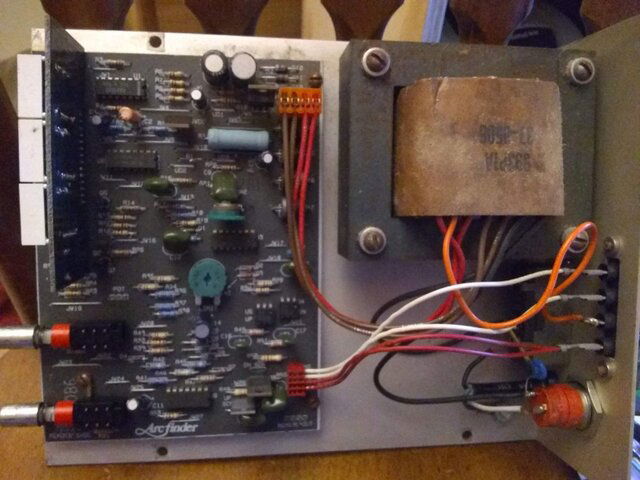
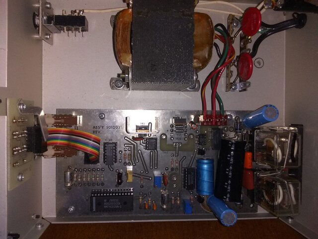
Here's inside pics of the Arc Finder box and one of the Sat Scan Boxes that I took yesterday. I haven't had time to mess with them since. Still doing some winterizing chores on the house and new well house. I ought to be ready for winter about May. LOL :rolleyes:

Arc_Finder.jpg Sat-Scan.jpg

* I mistakingly typed "Arc Scan" instead of Arc Finder before. I never found anything on-line about 'Arc Finder' except info about the former company. I'm messing with antiques that predate the internet.
 
Here's inside pics of the Arc Finder box and one of the Sat Scan Boxes that I took yesterday. I haven't had time to mess with them since. Still doing some winterizing chores on the house and new well house. I ought to be ready for winter about May. LOL :rolleyes:

View attachment 141664 View attachment 141665

* I mistakingly typed "Arc Scan" instead of Arc Finder before. I never found anything on-line about 'Arc Finder' except info about the former company. I'm messing with antiques that predate the internet.
Can you show us a picture from the front and backside ?
Its a strange positioner , I dont see relais for E / W , probably the 2 transistors do the job .
The two red wires from the connector at the circuitboard are both connected to contact 1 at the backside and at contact 2 is a wire straight from the transformer .
In most cases a positioner just let the actuator run a very short time when there is no feedback to the pot / reedsw. connectors .
So testing a actuator in that way is not very usefull .

Arc Finder inside.jpg
 
  • Like
Reactions: armadillo_115

Users Who Are Viewing This Thread (Total: 1, Members: 0, Guests: 1)

Latest posts

Top
Flash Sale Popup