Get the Best IPTV Service
Mechanical Limit Switches | SatelliteGuys.US

Mechanical Limit Switches

Status
Please reply by conversation.

RT-Cat

"My person-well trained"
Original poster
May 30, 2011
1,659
236
Cold, Cold,Michigan USA
It has been stated by a few the importance of mechanical limit switches on your actuator. One of my Thomson/Saginaw actuators has a nice set up under the cover. The other does not. Looking at the set up and putting the circuit on paper the operation was easy to understand. I have many different thoughts of building something, but have not totally decided on just what to come up with. My main thought is making sure to keep the weather away from the installation.
Has anyone actually set one up and willing to share what they came up with?
 
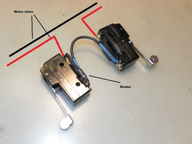
Trying to engineer a limit switch drive system in that actuator would be near impossible without an expense that would buy a new actuator with switches. The alternative would be to put switches on the mount. Lost Mesa found some switches and added them to a Birdview mount. Set up like this.

Apparently the image uploading has somehow been changed :(
 

Attachments

  • LimitSwitchs.jpg
    LimitSwitchs.jpg
    85.8 KB · Views: 255
I noticed the image upload different also. ???
Picture shows the same as I have on my drawing or layout. Looking for some way to keep the micro switches protected from the weather. I actually found a company that sells a kit, but the switches would be wet and dead in no time.
 
How about mercury switches? Don't know if you can even find them anymore. I have one here that is weatherized that you can have if you want it. If you want I can take a picture of it. You just have to figure where to mount the switches so that they open up for your limit. Then you just have to run the wiring to accomplish what you want to do. The switch I have is from an OLD system that used it for the extended limit switch.
 
A good idea, but I sort of made that attempt. I took an old round thermostat with a mercury switch in it and "played" with it at the dish with different positions. I really did not like the outcome. I have an idea on paper using a couple of IP66 waterproof small boxes to hold the micro switches. So far it "looks" like it may work. I just wish summer was not so short here now that we are going cold once again. Don't like outside work in the cold. I had enough of that when I was much younger building power lines.
Thanks for the suggestion.
 
I would trust a mechanical switch over a magnet and reed switch... Is it just me? :coco

The easiest retrofit on an actuator jack was to place the switches inside a small 5 sided rectangular poly box with the open side headed down to drain near the end of the tube. Both East/West switches were mounted against each other with the trigger arms exposed and riding against the extension tube. Drilled a hole for the East trigger to drop into at the desired east mechanical limit. Drilled a hole for the West trigger to drop into at the desired West mechanical limit.

On another job, mounted the box to the top horizontal reflector mount bar. Tacked an east and a a west nut to the top of the polar mount pivot tube and inserted 3-6" machine screws and locking nuts. Adjusted each screw to contact the trigger arm at the desired East and the West mechanical limits. Lost Mesa's mod inside the HH mount is very well done! :)

Maybe post a few photos of the mount and we could make more specific suggestions. So many different designs out there.
 
I would also rather use mechanical switches. My current design is with switches and some parts are on order.
This gives me something to play with mostly indoors now that the cold is working its way here. Not much fun outside when cold.
I'll let all know if the "thing" works.
 
  • Like
Reactions: . Raine
Well, parts arrived and first unit construction looks OK. It should do the job. The plastic boxes I found had three pre-drilled holes for wire glands and I only need one. So right now the box is waiting for the JB weld to harden to plug up the extra holes. After I take an ambition pill(joke)I will start working on the other box.
I have to drive a big truck to Kentucky next week so that is going to take me away from my toys for a few days.
 
  • Like
Reactions: KE4EST and Titanium
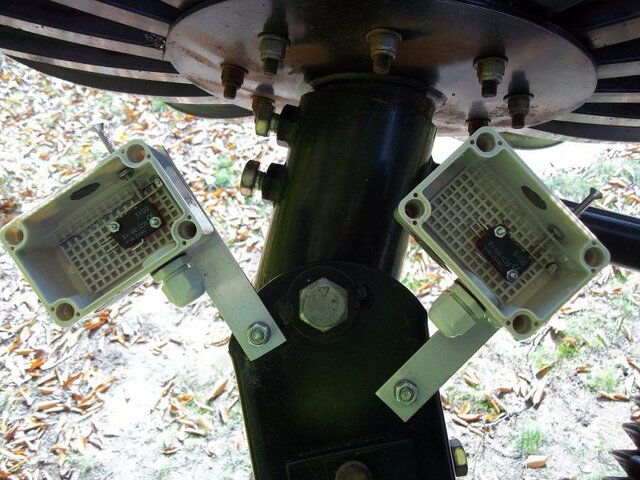
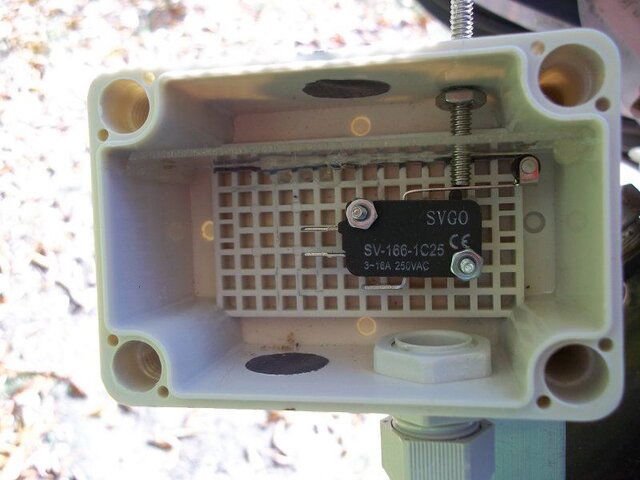
I have the limit switches constructed and installed. The pictures show the mounted boxes without the wires installed yet. I finished this afternoon and they actually work. There is a clear piece of plastic hot glued inside that helps support the ss screw that comes through the box. I have a small piece of an inner tube that the bolt goes through and is epoxied to the outside of the box to keep water from getting inside. The dark spots are pre-drilled holes that I filled with JB weld. The grid in the bottom of the box is not removable and did not cause any problem. Operation is rather obvious. The back center plate of the dish pushes the screw into the micro switch and dish stops. Not as good as my other actuator that the manufactured built one inside, but this should work.
Limit Box 1.JPG Limit Box Big.JPG
 
Status
Please reply by conversation.

Users Who Are Viewing This Thread (Total: 1, Members: 0, Guests: 1)

Who Read This Thread (Total Members: 2)

Latest posts

Top
Flash Sale Popup